2020 Season – Infinite Recharge
2020 Season
Infinite Recharge
Worth a Mention
- Machined (in-house):
-
- Drive chassis — routered from box tubing
- Axle for the shooter wheels — custom lathe work
- Intake rails, brackets, shooter base plate, and other structural elements — routered in-house
- Laser-Cut (in-house):
- Custom Delrin turret, intake HDPE plates
- 3D-Printed (in-house):
- DIN rail mounts, pulleys, and all sorts of other things!
- Heat Transferred (in-house):
- Bumper numbers (also cut in-house on a mentor's Cricut)
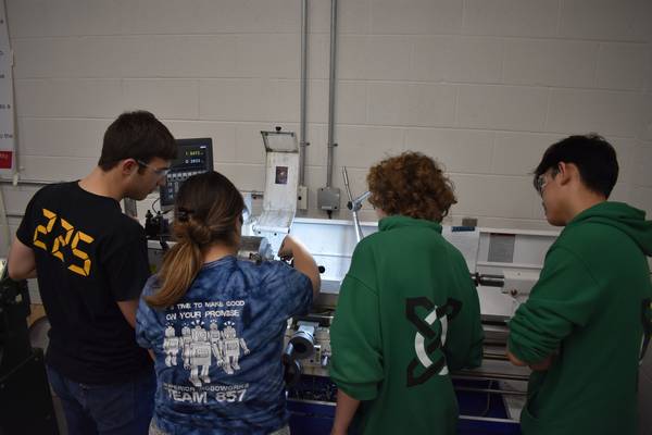
A group of Celt-X students using the lathe. For more images, visit the 2020 Gallery.
The only parts of the robot that was not made in-house were the
bumper frames, which were waterjetted and bent on a CNC brake at
one of our sponsors. Without a CNC brake, it would have been
extremely difficult to achieve the precise bends we wanted for our
bumper frames.
This season, we faced an interesting problem — how to machine box
tubing. This was a significant challenge for us on the router, but
we developed a procedure where we could align, probe, and flip the
tubing to get matching holes (e.g. for bearings) on both sides.
Learned From Past Years
This year, we set a goal to have zero on-field breakdowns. Here's what we learned from past years in order to try to reach our goal:
- No POE on Limelight:
- Having POE on the Limelight introduces more points of failure and increases the likelihood of losing the Limelight if the connection is just a little bit off. Instead, the Limelight is wired straight into the PDP.
- IDC Connectors:
- We use IDC connectors on our CAN bus to connect each node to the main bus. This provides a secure connection and ensures that a failure of any wires going to a node does not result in the failure of the main bus, which keeps the system operating more reliably.
- Ethernet Switch for Tethering:
- Utilized so nothing has to be unplugged when we tether on the practice field. This increases reliability because we don't need to check if we forgot to plug something back in.
- DIN Rail Mounts:
- Our mounts are custom 3D-printed in-house and simply clip onto the DIN rail — this makes it easy to remove and fix any motor controller issues. Being able to securely mount electronics in an industry standard way and then remove and reposition them as needed makes replacement and maintenance easy. Because the DIN rail was so successful in 2019, we continued using it for 2020.
Software and Controls
- Sensors:
- NavX (gyro and accelerometer), NEO encoders, SRX MAG encoders, Limelight for vision tracking
- Motor Controllers:
- SPARK MAXs controlling the NEOs and NEO 550s, via CAN
- Autonomous:
- Ramsete Controller for path following, utilizing parallel and sequential commands
- Baselock:
- To combat defense while stationary, the drive motor controllers are instructed to actively hold the last position they were in. This makes the robot harder to knock around while shooting.
- Pulsed Rollers:
- Since Mo's hopper is just controlled by gravity, the intake rollers need to be pulsed to "push" the Power Cells into the feeder. They also help to jostle the Power Cells around a bit to promote natural reordering and some amount of anti-jamming.
- Velocity-Controlled Feeder:
- In order to maintain shooting accuracy, it is important to give the shooter wheel some minimum time to recover. By controlling the speed of the mechanism that is feeding Power Cells into the shooter flywheel, we can ensure a minimum time between Power Cells, which is timed to ensure that the flywheel velocity will be sufficient for the next shot by the time the ball enters the shooter.
- Absolute Encoders, Auto-Targeting, Soft Limits:
-
- There are two absolute encoders — one on the turret itself and one on the hood. That way, if we lose communication to the robot, we can always know the position of our mechanism from any arbitrary location. Having absolute encoders also means that we don't have to zero out our mechanisms when turning on the robot. This eliminates a step in our match preparation, which increases reliability.
- We use the retro-reflective markers with the Limelight's built in machine vision to locate targets. We use the horizontal offset to position the turret, and use a quadratic regression on the target's vertical offset to calculate the hood angle and flywheel RPM from any location on the field.
- The ~300 degrees of turret rotation is a conservative estimate — soft limits have been implemented to ensure we don't break our umbilical while turning the turret. (It is worth noting that while Mo's turret could rotate 360 degrees, we would damage the umbilical.)
- Automated Climb:
- To activate the automated climb, first the driver lines up with the Shield Generator switch and presses a one-button combo. The arms then go to a fixed height and the operator can adjust from there. To make the climb, it is one more one-button combo. We use button combos to trigger actions that we don't want to happen by accident.
Performance
- Can shoot Power Cells into the Inner and Outer Port at a speed of two balls per second
- Can climb on the Shield Generator switch in 3 seconds
- Can go through the trench run
- Can shoot from as far as 30ft away from the driver wall
Events and Outreach
- FIRST Aid Day:
- Helped multiple teams to either get their robots driving or to implement additional functionality (February 2020)
- HWCDSB System Science Fair:
- Talked to students about FIRST robotics with 4039 MakeShift and demoed Pat, our practice bot for Infinite Recharge (March 2020)